honeywell zone valve wiring pdf
Category : PDF
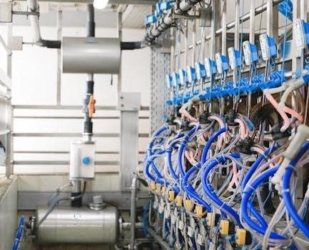
Honeywell zone valves are essential components in zoned HVAC systems, controlling the flow of water or steam to different zones. They ensure efficient heating by directing resources only where needed, optimizing comfort and energy use. Proper wiring is crucial for their operation, as highlighted in Honeywell zone valve wiring diagrams, which guide installers through connections for models like the V8043 and V4043. These valves are designed for silent operation and compatibility with various systems, including S Plan and Y Plan configurations, making them versatile for different heating setups.
1.1 Overview of Honeywell Zone Valves
Honeywell zone valves are critical components in zoned HVAC systems, regulating water or steam flow to specific areas. Models like the V8043 and V4043 are designed for efficient operation, ensuring optimal heating and energy savings. These valves are known for their silent operation and compatibility with various systems, including S Plan and Y Plan configurations. They are often used in hydronic heating systems, providing precise control over temperature zones. Proper installation, guided by Honeywell zone valve wiring diagrams, is essential for their functionality. These diagrams detail connections for thermostats, pumps, and other components, ensuring seamless integration into zoned heating setups.
1.2 Importance of Proper Wiring
Proper wiring is crucial for the safe and efficient operation of Honeywell zone valves. Incorrect connections can lead to system malfunctions, energy waste, or even safety hazards. Honeywell zone valve wiring diagrams provide detailed guidance to ensure accurate connections, minimizing risks and optimizing performance. These diagrams outline the correct wire assignments for components like thermostats, actuators, and power sources. Adhering to the specified wiring configurations ensures reliable valve operation, maintains system efficiency, and prolongs equipment lifespan. Improper wiring can void warranties and compromise the valve’s ability to regulate zones effectively, highlighting the necessity of following official Honeywell documentation and guidelines.

Understanding the Honeywell Zone Valve Wiring Diagram
A Honeywell zone valve wiring diagram is a visual guide showing electrical connections, components, and their interactions. It helps installers understand how to connect wires correctly for smooth operation.
2.1 What is a Wiring Diagram?
A wiring diagram is a detailed visual representation of electrical connections and components in a system. For Honeywell zone valves, it illustrates how wires connect to the valve, thermostat, and boiler. The diagram uses symbols and labels to show each part’s role and their relationships. It serves as a blueprint for installers, simplifying complex connections. The Honeywell zone valve wiring PDF typically includes this diagram, ensuring proper installation and troubleshooting. By following the diagram, technicians can identify the correct terminals and avoid errors. It is an essential tool for understanding and working with the zone valve system safely and effectively.
2.2 Key Components of the Wiring Diagram
A Honeywell zone valve wiring diagram includes several key components essential for proper installation and operation. These components are clearly labeled and represented using industry-standard symbols. They include the zone valve itself, the thermostat, the boiler or heating system, and the wiring connections between these devices. The diagram also highlights terminals, such as the common (C), live (L), and neutral (N) terminals, as well as any auxiliary connections; Color-coded wires are often used to differentiate between power, ground, and signal wires. A legend or key is usually provided to explain the symbols and abbreviations used, ensuring clarity for installers and technicians.
2.3 How to Read the Wiring Diagram
Reading a Honeywell zone valve wiring diagram requires understanding its components and connections. Start by identifying the key elements: the zone valve, thermostat, and boiler. Locate the terminals labeled as C (common), L (live), and N (neutral). These labels indicate where wires should be connected. Follow the color-coded wires to trace their paths between components. Use the diagram’s legend to interpret symbols, ensuring you understand each representation. Begin from the power source, trace through the thermostat, and follow the connections to the zone valve and boiler. This methodical approach helps in setting up the system correctly and troubleshooting issues efficiently.
Honeywell Zone Valve Models
Honeywell offers various zone valve models, including the popular V8043 and V4043, each designed for specific heating systems and wiring configurations. These models ensure precise temperature control and energy efficiency.
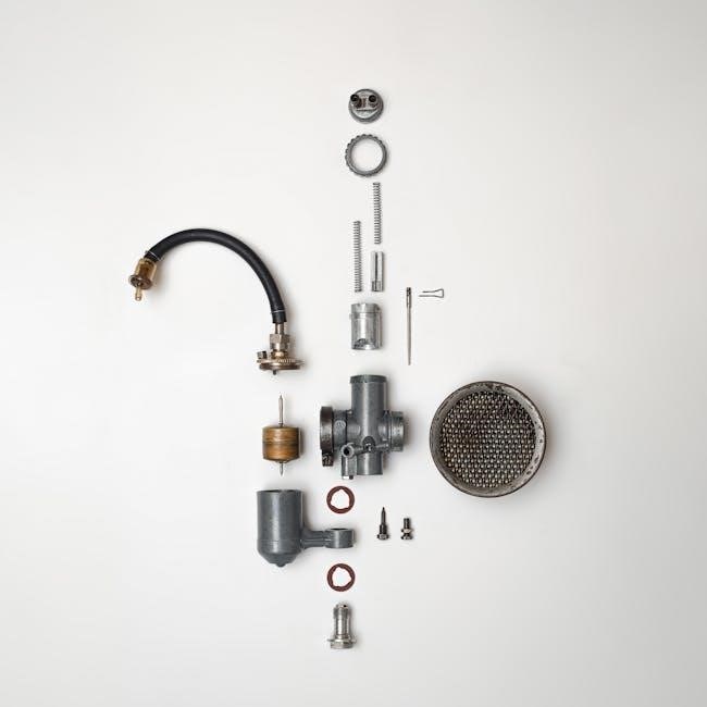
3.1 V8043 Zone Valve
The V8043 zone valve is a popular model designed for hydronic heating systems, offering reliable performance and precise control. It features a 2-wire or 3-wire configuration, making it versatile for various installations. This valve is compatible with both 24V and 230V systems, ensuring flexibility. Its compact design and durable construction make it a preferred choice for zoning heating systems. The V8043 is known for its low power consumption and quiet operation, enhancing energy efficiency. Proper wiring, as detailed in the Honeywell zone valve wiring PDF, is essential for optimal functionality and safety. It supports both S Plan and Y Plan configurations, catering to different system requirements. Regular maintenance, such as cleaning and lubrication, ensures long-term reliability. This model is widely used in residential and commercial settings due to its dependability and ease of integration with thermostats and controllers. Always refer to the official Honeywell documentation for specific installation guidelines to avoid wiring errors.
3.2 V4043 Zone Valve
The V4043 zone valve is a 4-port, mid-position valve designed for hydronic heating systems. It operates on a 3-wire configuration, allowing for precise control of water flow between heating zones. This model is compatible with both 24V and 230V systems, making it versatile for various installations. The V4043 is known for its energy efficiency and quiet operation, ensuring minimal noise during use. It is ideal for systems requiring multiple zones, such as S Plan Plus and Y Plan configurations. Proper wiring, as outlined in the Honeywell zone valve wiring PDF, ensures smooth operation. Regular maintenance, like cleaning and checking electrical connections, is essential for longevity. The V4043 is a reliable choice for zoned heating systems, offering consistent performance and compatibility with modern controllers. Always refer to the official Honeywell documentation for specific installation and wiring guidelines.
3.3 Other Models and Their Variations
Beyond the popular V8043 and V4043 models, Honeywell offers a range of other zone valves tailored to specific heating systems. The V5050 and V5070 models, for instance, are designed for advanced zoned heating setups, with features like 5-wire and 7-wire configurations. These valves are ideal for systems requiring precise temperature control and compatibility with smart home systems. Additionally, Honeywell provides wireless and programmable zone valves, such as the VH Series, which integrate seamlessly with modern thermostats. Each model has unique wiring requirements, making it essential to consult the Honeywell zone valve wiring PDF for accurate installation. These variations ensure flexibility and efficiency in zoned heating applications. Always check compatibility with your system before installation. Proper wiring ensures optimal performance and energy efficiency. Regular maintenance and adherence to wiring guidelines prolong the lifespan of these valves. Honeywell’s diverse range caters to both residential and commercial needs.
Installation and Wiring Requirements
Proper installation and wiring are critical for Honeywell zone valves to ensure safe and efficient operation. Always follow the Honeywell zone valve wiring PDF guidelines. Use appropriate tools and materials, and ensure compatibility with your heating system for optimal performance and safety. Adhere to all safety precautions and manufacturer recommendations to avoid damage or hazards. Correct wiring ensures precise control and energy efficiency, while preventing potential malfunctions. Regular inspections and maintenance are essential to uphold system reliability and longevity. Follow the specified wiring configurations to guarantee seamless integration with your zoned heating setup. Proper installation is key to maximizing the valve’s lifespan and functionality.
4.1 Tools and Materials Needed
Installing Honeywell zone valves requires specific tools and materials to ensure proper setup. Essential tools include an adjustable wrench, screwdrivers, pliers, and a multimeter for wiring checks. Materials needed are copper piping, fittings, and wiring connectors. Ensure compatibility with your system by referencing the Honeywell zone valve wiring PDF. Additional items like Teflon tape, pipe cutters, and a drain key may be necessary for plumbing connections. Always verify the specific requirements for your model, as some valves may need additional components. Gather all materials beforehand to streamline the installation process and avoid delays. Proper tools ensure secure and leak-free connections.
4.2 Step-by-Step Installation Guide
Begin by turning off the power and water supply to the system. Mount the Honeywell zone valve in an accessible location, ensuring proper alignment with the piping. Connect the valve to the system’s actuator, following the wiring diagram from the Honeywell zone valve wiring PDF. Attach the wires to the terminal block, ensuring correct polarity. Secure the valve to the pipe using appropriate fittings and tighten gently. Once installed, turn the power and water supply back on. Test the valve by activating it via the thermostat or control system. Double-check all connections for leaks and proper function. Refer to the PDF for specific model instructions.
4.3 Safety Precautions
Always disconnect the power supply before starting any wiring or installation work. Ensure the water system is drained or turned off to prevent water damage or flooding. Wear protective gear, including gloves and safety glasses, to avoid injury. Use tools appropriately to avoid damaging the valve or surrounding components. Follow the Honeywell zone valve wiring PDF instructions carefully to prevent electrical hazards. Never attempt to test the valve under power without proper connections. Keep the area clear of flammable materials, as electrical work may pose fire risks. Ensure the system is depressurized before servicing to avoid sudden water release. Always ground the system properly to prevent electrical shocks.
Common Wiring Configurations
Honeywell zone valves support various wiring configurations, including 2-wire, 3-wire, and 5-wire setups, catering to different system requirements such as heat pumps or bypass valves.
5.1 2-Wire Zone Valve Wiring
A 2-wire zone valve wiring configuration is a common setup for Honeywell zone valves, typically used in systems with a single zone or basic control requirements. This configuration involves two wires: one for power and one for control. It is ideal for systems where the valve is controlled directly by a thermostat or a simple on/off switch. The 2-wire setup simplifies installation and is energy-efficient, as it uses the same wires for both power supply and control signals. This configuration is widely used in heating systems and is compatible with most Honeywell zone valve models, including the V8043 and V4043 series.
5.2 3-Wire Zone Valve Wiring
A 3-wire zone valve wiring configuration is commonly used for two-position control, enabling the valve to operate in either fully open or fully closed positions. This setup includes a live wire, a neutral wire, and an earth wire, providing a safe and reliable connection. The live wire powers the valve, while the neutral completes the circuit. This configuration is ideal for systems requiring precise control, such as hydronic heating systems. The 3-wire setup is compatible with Honeywell models like the V8043 and V4043, offering flexibility and efficiency. It ensures smooth operation and is widely recommended for systems with multiple zones or complex control needs.
5.3 5-Wire Zone Valve Wiring
The 5-wire zone valve wiring configuration is designed for advanced control systems, offering enhanced functionality and compatibility with modern heating systems. This setup typically includes wires for power, control signals, and feedback, enabling precise modulation and communication between the valve and the control system. It is commonly used in zoned heating systems with multiple thermostats or smart home integrations. Honeywell models like the V8043 and V4043 often support this configuration, allowing for efficient energy management and seamless integration with smart thermostats. The 5-wire setup is ideal for complex systems requiring detailed control and monitoring, ensuring optimal performance and energy efficiency.
Troubleshooting Honeywell Zone Valve Wiring
Troubleshooting Honeywell zone valve wiring involves identifying common issues like short circuits, faulty connections, or incorrect configurations. Always refer to the Honeywell wiring diagram PDF for guidance. Ensure all wires are securely connected and verify power supply. Check for signs of wear or damage. If issues persist, consult the official Honeywell documentation or contact a certified technician for assistance. Regular maintenance and inspections can prevent wiring problems, ensuring reliable system operation.
6.1 Common Wiring Issues
Common wiring issues with Honeywell zone valves include loose connections, incorrect wire polarity, and short circuits. Overloaded systems or incorrect wire gauge can also cause malfunctions. Corrosion or damaged wires may lead to intermittent operation. Additionally, improper wiring configuration, such as mixing line and neutral wires, can disrupt valve function. Always refer to the Honeywell wiring diagram PDF for correct connections. Regular inspections and proper maintenance can help identify and resolve these issues early, ensuring reliable system performance. Addressing these problems promptly prevents more severe damage and ensures optimal heating or cooling control.
6.2 How to Identify and Fix Short Circuits
To identify short circuits in Honeywell zone valves, look for signs like the valve failing to open or close, or unusual currents. Turn off the power supply and inspect wires for visible damage or improper connections. Use a multimeter to test for short circuits between wires or terminals. If a short is detected, disconnect the faulty wire and repair or replace it. Ensure all connections are secure and follow the Honeywell wiring diagram PDF for correct configurations. After repairs, turn the power back on and test the system. If issues persist, consider replacing the valve or consulting a professional.
6.3 Resetting the Zone Valve System
To reset a Honeywell zone valve system, start by turning off the power supply at the circuit breaker. Disconnect the wires from the valve and wait 10-15 minutes to allow any residual charge to dissipate. Reconnect the wires according to the Honeywell wiring diagram PDF. Turn the power back on and test the valve by operating the thermostat or control system. If the valve still doesn’t function, check for internal damage or faulty components. Resetting may resolve issues like stuck valves or incorrect wiring configurations. Always refer to the official Honeywell documentation for specific reset procedures for your model.

Honeywell Zone Valve Wiring for Different Systems
Honeywell zone valves adapt to various HVAC systems, including S Plan and Y Plan configurations, ensuring efficient zoned heating setups. Refer to the Honeywell wiring diagram PDF for specific system compatibility.
7.1 S Plan Wiring Configuration
The S Plan configuration is a popular setup for zoned heating systems, utilizing a conventional boiler with a separate programmer and room thermostat. In this configuration, the Honeywell zone valve controls water flow to specific zones based on the thermostat’s demand. The wiring involves connecting the zone valve to the boiler, programmer, and thermostat, ensuring synchronized operation. The Honeywell wiring diagram PDF provides detailed connections for S Plan setups, highlighting the correct terminals for power, neutral, and control wires. This configuration is ideal for systems requiring precise temperature control and zoning flexibility. Proper wiring ensures efficient and reliable performance of the heating system.
7.2 Y Plan Wiring Configuration
The Y Plan wiring configuration is commonly used with combi boilers, offering a streamlined setup for heating systems. It employs a three-port valve, simplifying the control of water flow to different zones. In this configuration, the Honeywell zone valve is connected to the combi boiler, thermostat, and programmer, ensuring synchronized operation. The Honeywell wiring diagram PDF provides detailed guidance, highlighting connections for live, neutral, and control wires. This setup is ideal for systems needing efficient temperature control without separate hot water management. Proper wiring ensures reliable performance, with the zone valve opening or closing based on thermostat demand, optimizing heating efficiency.
7.3 Zoned Heating Systems
Zoned heating systems allow precise temperature control in different areas of a building, enhancing comfort and energy efficiency. Honeywell zone valves are integral to these systems, enabling hot water distribution to specific zones based on thermostat demand. Each zone is equipped with a zone valve, ensuring independent operation. The wiring connects the valves to the system’s controls, such as the boiler and programmer. Proper installation ensures seamless communication between components. Zoned systems reduce energy waste by only heating occupied areas, making them ideal for larger properties. Honeywell’s wiring diagrams provide clear guidance for configuring these systems, ensuring optimal performance and efficiency.
Honeywell Zone Valve and Thermostat Integration
Honeywell zone valves integrate seamlessly with thermostats, optimizing zoned heating performance. Proper wiring ensures precise communication between valves and thermostats, enhancing energy efficiency and comfort.
8.1 Connecting the Zone Valve to a Thermostat
To connect a Honeywell zone valve to a thermostat, refer to the wiring diagram in the Honeywell zone valve wiring PDF. Identify the appropriate terminals on both devices. Connect the common wire from the thermostat to the designated terminal on the zone valve. Next, attach the zone wires to the corresponding terminals, ensuring proper polarity. Verify compatibility between the thermostat and zone valve to ensure seamless communication. Follow the step-by-step instructions in the PDF for accurate connections. After wiring, test the system to confirm proper functionality. Always turn off power before starting work and consult official documentation or a professional if unsure.
8.2 Smart Thermostat Compatibility
Most Honeywell zone valves are compatible with smart thermostats, enhancing zoned heating control. Ensure compatibility by checking the Honeywell zone valve wiring PDF for specific models like the V8043 or V4043. Smart thermostats such as Nest, Ecobee, or Honeywell Home models often integrate seamlessly. Connect the zone valve wires to the thermostat’s corresponding terminals, following the wiring diagram. Smart thermostats enable advanced features like remote scheduling, geofencing, and energy monitoring. Verify compatibility with your system to optimize performance. Always consult the Honeywell wiring guide for detailed instructions specific to your setup. Proper installation ensures efficient and smart zoned heating operation.
8.3 Programming the Thermostat for Zoned Heating
Programming a thermostat for zoned heating involves setting up temperature zones and schedules. Start by identifying each zone and assigning it to the corresponding Honeywell zone valve. Use the Honeywell zone valve wiring PDF to ensure correct connections. Set temperature preferences for each zone based on occupancy or lifestyle. Schedule heating times to match daily routines, optimizing energy use. Advanced thermostats allow geofencing or smart learning to adapt settings automatically. After programming, test the system to ensure smooth operation across all zones. Proper programming enhances comfort and efficiency, preventing unnecessary heating in unoccupied areas. Refer to the Honeywell wiring guide for detailed instructions.
Maintenance and Upkeep of Honeywell Zone Valves
Regular maintenance ensures Honeywell zone valves operate efficiently. Check for wear, clean components, and ensure wiring is secure to prevent potential issues and extend lifespan.
9.1 Cleaning the Zone Valve
Cleaning the Honeywell zone valve is essential for maintaining its performance and preventing malfunction. Start by turning off the power supply and allowing the valve to cool. Use a soft cloth or brush to remove dirt, dust, or debris from the exterior and internal components. Avoid harsh chemicals, as they may damage the valve’s materials. For stubborn dirt, compressed air can be gently applied. Regular cleaning ensures proper operation and prevents issues like stuck valves or wiring problems. Always refer to the Honeywell zone valve wiring PDF for specific cleaning recommendations tailored to your model.
Tip: Clean the valve every 6-12 months to maintain efficiency and reliability.
9.2 Lubricating Moving Parts
Lubricating the moving parts of your Honeywell zone valve ensures smooth operation and prevents wear. Use a silicone-based lubricant, as it is non-conductive and safe for electrical components. Apply a small amount to the valve stem and bonnet area, avoiding excessive use that could attract dust. Lubrication should be done every 12-18 months or when noise or resistance is detected. Refer to the Honeywell zone valve wiring PDF for specific lubrication points and recommendations. Proper lubrication extends the valve’s lifespan and maintains efficient heating system performance.
Tip: Always test the valve after lubrication to ensure proper function.
9.3 Regular Inspection of Wiring
Regular inspection of the wiring in your Honeywell zone valve system is crucial for maintaining optimal performance and safety. Check all connections for tightness and ensure no wires are loose or damaged. Inspect cables for signs of wear, fraying, or corrosion, and replace them if necessary. Verify that all wires are correctly color-coded and connected according to the Honeywell zone valve wiring PDF. This guide provides detailed diagrams to help identify proper connections. Schedule inspections annually or after any system modification to prevent issues like short circuits or malfunctioning valves.
Tip: Use a multimeter to test for continuity and ensure proper wiring integrity.

Honeywell Zone Valve Wiring Resources
Access the Honeywell zone valve wiring PDF for detailed diagrams and instructions. Consult official Honeywell documentation and online forums for additional support and troubleshooting tips.
10.1 Honeywell Wiring Diagram PDF
The Honeywell zone valve wiring PDF is a comprehensive guide providing detailed diagrams for various zone valve models. It includes step-by-step instructions for installation, troubleshooting, and maintenance. The PDF covers wiring configurations for 2-wire, 3-wire, and 5-wire systems, ensuring compatibility with different heating setups. Users can download it from Honeywell’s official website or authorized distributors. This resource is essential for technicians and DIY enthusiasts, offering clear visuals and explanations. It also outlines safety precautions and best practices for wiring zone valves. Referencing this PDF ensures proper installation and operation of Honeywell zone valves in zoned heating systems.
10.2 Official Honeywell Documentation
Official Honeywell documentation provides detailed guides for zone valve wiring, ensuring compliance with manufacturer specifications. These resources include user manuals, technical data sheets, and application guides. They cover installation, configuration, and troubleshooting for various zone valve models. The documentation is designed for professionals and homeowners alike, offering clear instructions and safety guidelines. Official Honeywell documents are available on their website or through authorized distributors. They are essential for understanding specific wiring requirements and ensuring optimal performance of Honeywell zone valves in zoned heating systems. Always refer to official documentation for accurate and reliable information.
10.3 Online Forums and Communities
Online forums and communities are invaluable resources for troubleshooting and understanding Honeywell zone valve wiring. Platforms like Reddit, HVAC forums, and DIY home improvement communities often feature discussions where experts and homeowners share experiences. These forums provide practical advice, tips, and solutions to common wiring issues. Many users upload and share Honeywell zone valve wiring PDFs, diagrams, and guides. While official documentation is crucial, forums offer real-world insights and peer support; Engaging with these communities can help resolve specific challenges and provide alternative perspectives for successful installations. Always verify advice with official sources to ensure accuracy and safety.
Proper wiring of Honeywell zone valves ensures efficient heating control. Use official diagrams and resources for accurate installations. Consult guides for troubleshooting and optimal performance.
11.1 Summary of Key Points
The Honeywell zone valve wiring process requires careful attention to diagrams and manufacturer instructions. Proper wiring ensures efficient system operation, while incorrect setups can lead to malfunctions. Key points include understanding the wiring diagram, identifying components, and following step-by-step installation guides. Regular maintenance, like cleaning and lubricating valves, extends longevity. Troubleshooting common issues, such as short circuits, is essential for system reliability. Integration with thermostats, especially smart models, enhances control and efficiency. Always refer to official Honeywell resources, like the wiring PDF, for accurate guidance. Proper installation and upkeep ensure optimal performance and energy savings in zoned heating systems.
11.2 Final Tips for Successful Wiring
For successful Honeywell zone valve wiring, always follow the official PDF guide to avoid errors. Double-check all connections before powering up the system to ensure safety and proper function. Use the correct tools and materials to prevent damage to the valve or wiring. Test the system thoroughly after installation to identify and address any issues early. Keep the wiring diagram handy for reference during troubleshooting. Regularly inspect and maintain the system to ensure long-term efficiency. By adhering to these tips, you can achieve a reliable and efficient zoned heating setup with your Honeywell zone valve.