anatomy and physiology lab manual
Category : Manuals
The Anatomy and Physiology Lab Manual serves as a comprehensive guide for hands-on exploration of the human body, integrating theoretical knowledge with practical lab experiences.

1.1 Purpose and Scope of the Lab Manual
The purpose of the Anatomy and Physiology Lab Manual is to provide students with a structured framework for exploring human anatomy and physiology through hands-on experiments and observations. It serves as a practical companion to textbooks, offering step-by-step procedures for conducting lab activities. The scope includes experiments on histology, physiological measurements, and dissection, ensuring a comprehensive understanding of anatomical structures and physiological processes. This manual also emphasizes safety protocols, proper use of equipment, and accurate data interpretation, preparing students for professional medical education and research environments.
1.2 Importance of Anatomy and Physiology in Medical Education
Anatomy and physiology form the foundation of medical education, enabling students to understand the structure and function of the human body. These disciplines are essential for developing diagnostic and surgical skills, as well as for understanding disease mechanisms. Hands-on lab experiences reinforce theoretical knowledge, allowing students to apply concepts to real-world scenarios. Mastery of anatomy and physiology is critical for healthcare professionals, as it directly impacts patient care and treatment outcomes. It bridges the gap between basic sciences and clinical practice, ensuring a comprehensive understanding of human health and disease.
Essential Lab Equipment and Tools
The anatomy and physiology lab requires specific equipment, including microscopes, dissecting tools, and measurement devices, to facilitate accurate observations and effective hands-on learning experiences.
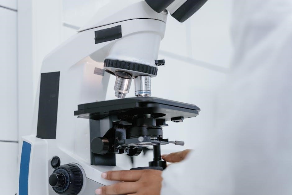
2.1 Microscopes and Their Accessories
In anatomy and physiology labs, microscopes are indispensable for examining cellular and tissue structures. Essential accessories include slides, cover slips, and staining solutions to prepare specimens for observation. Compound light microscopes are commonly used for detailed tissue analysis, while stereomicroscopes provide three-dimensional views of larger structures. Accessories like immersion oil enhance resolution, and digital cameras enable capturing images for further study. Proper handling and maintenance of these tools ensure accurate observations and prolong equipment lifespan, making them vital for effective lab work.
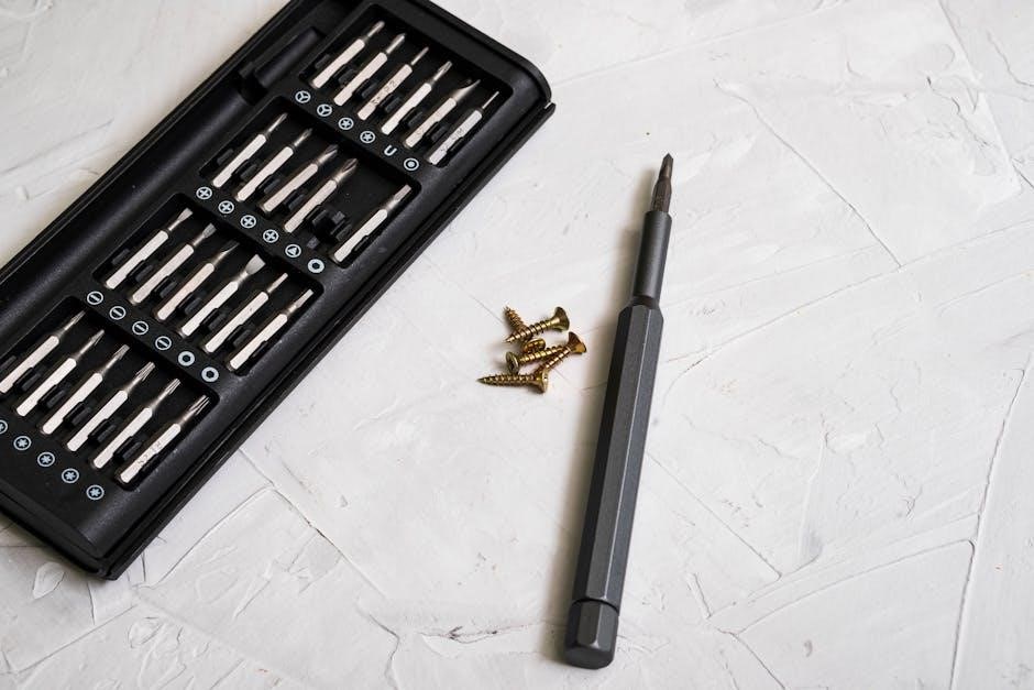
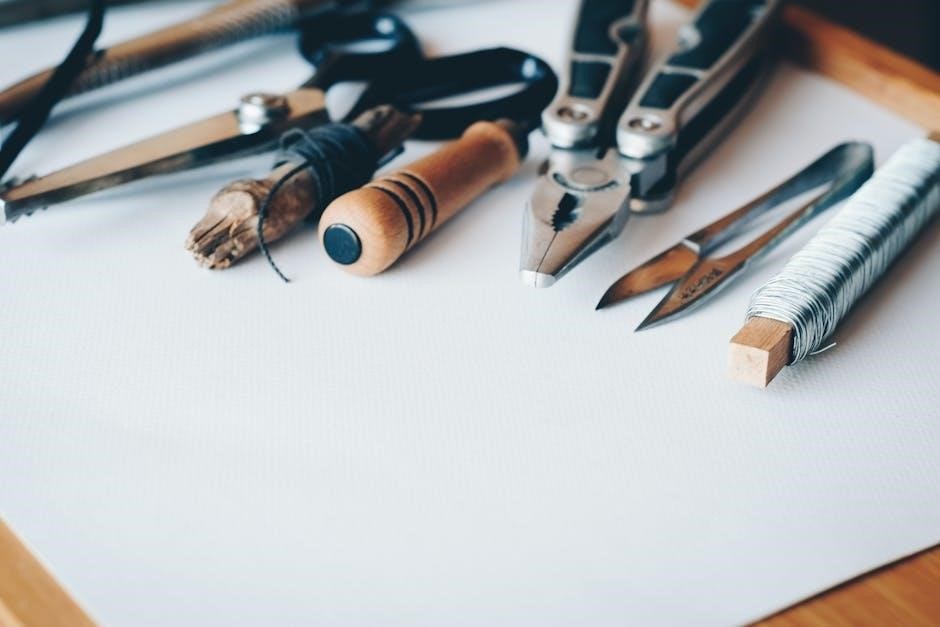
2;2 Dissection Instruments and Their Uses
Dissection instruments are vital for anatomy and physiology labs, enabling precise exploration of biological specimens. Common tools include scalpels, forceps, and dissecting scissors, each designed for specific tasks. Scalpels are used for making incisions, while forceps handle delicate tissues. Dissecting scissors are ideal for cutting through connective tissue. Proper use and maintenance of these instruments ensure safety and prevent damage. Students must follow safety protocols to avoid accidents and contamination, making these tools indispensable for effective lab dissection and specimen analysis.
Safety Protocols in the Anatomy and Physiology Lab
Safety protocols are essential to prevent accidents and ensure a secure lab environment. Proper handling of biological specimens, chemicals, and equipment is critical to avoid contamination and injury.
3.1 Handling Biological Specimens Safely
Handling biological specimens requires strict adherence to safety protocols to minimize risks. Always wear personal protective equipment (PPE), such as gloves and lab coats, when interacting with specimens. Ensure proper storage and labeling of biological materials to avoid contamination. Dispose of waste in designated biohazard containers, and decontaminate surfaces after use. Avoid direct contact with potentially infectious specimens, and follow autoclaving procedures for sterilization. Familiarize yourself with emergency procedures in case of exposure or spills.
- Use appropriate tools to handle specimens to prevent direct contact.
- Check for signs of damage or decay before handling specimens.
3.2 Chemical Safety and Waste Disposal
Chemical safety and proper waste disposal are critical in anatomy and physiology labs to prevent accidents and environmental harm. Always read and follow the Safety Data Sheets (SDS) for chemicals. Wear appropriate PPE, such as gloves and goggles, when handling hazardous substances. Store chemicals in labeled, sealed containers and dispose of waste in designated receptacles. Use fume hoods for volatile chemicals and ensure proper ventilation. Never mix chemicals without prior knowledge of their reactions, and adhere to lab-specific disposal guidelines for biological and chemical waste.
- Use tongs or spatulas to handle chemicals when possible.
- Label waste containers clearly and dispose of them according to regulations.
Common Lab Experiments and Exercises
Lab exercises include histology slide preparation, physiological measurements, and dissection of specimens. Students explore cellular structures and analyze body functions through hands-on activities.
- Histology slide staining and microscopy analysis.
- Measuring heart rate, blood pressure, and respiratory rate.
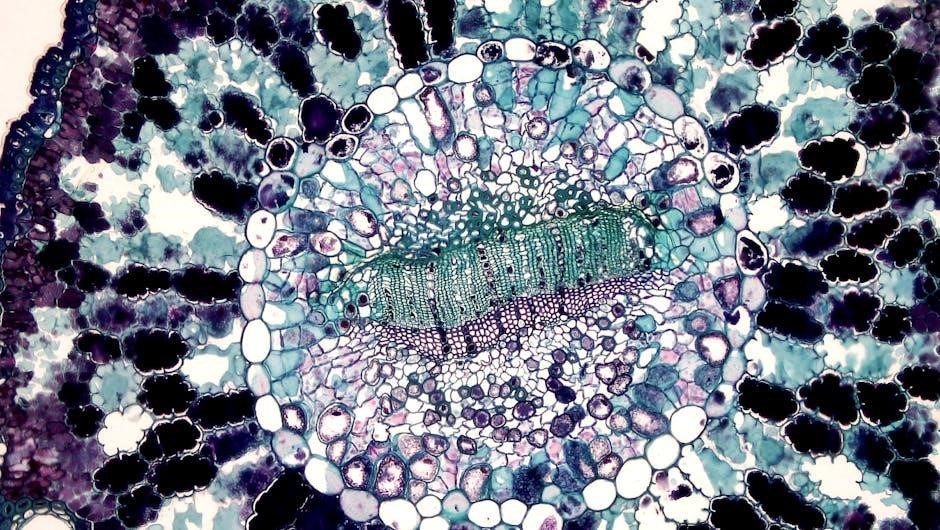
4.1 Histology Slide Preparation and Analysis
Histology slide preparation involves fixing, sectioning, staining, and mounting tissues to study cellular structures under a microscope. Students learn to identify tissue types, such as epithelial and connective tissues, and their functions. Proper staining techniques, like hematoxylin and eosin (H&E), are essential for clear visualization. Analysis includes observing cell morphology, arrangement, and specialized features. This exercise enhances understanding of tissue organization and its role in overall physiology. Accurate slide preparation and interpretation are critical skills for medical and biological sciences.
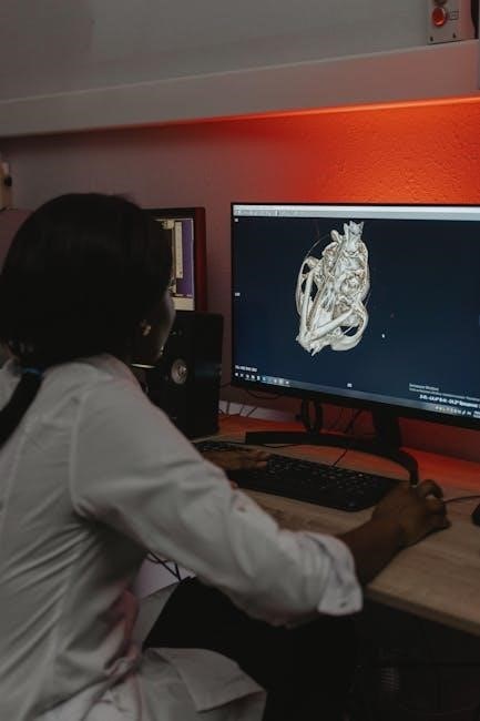
4.2 Physiological Measurements and Data Interpretation
Physiological measurements involve collecting data on bodily functions, such as heart rate, blood pressure, and respiratory rate. Students use tools like ECG, spirometry, and blood pressure monitors to gather accurate readings. Data interpretation requires analyzing trends, calculating metrics like mean and standard deviation, and correlating findings with physiological concepts. This exercise enhances understanding of human function and prepares students for clinical applications. Accurate recording and analysis are essential for drawing meaningful conclusions and applying knowledge in real-world scenarios.
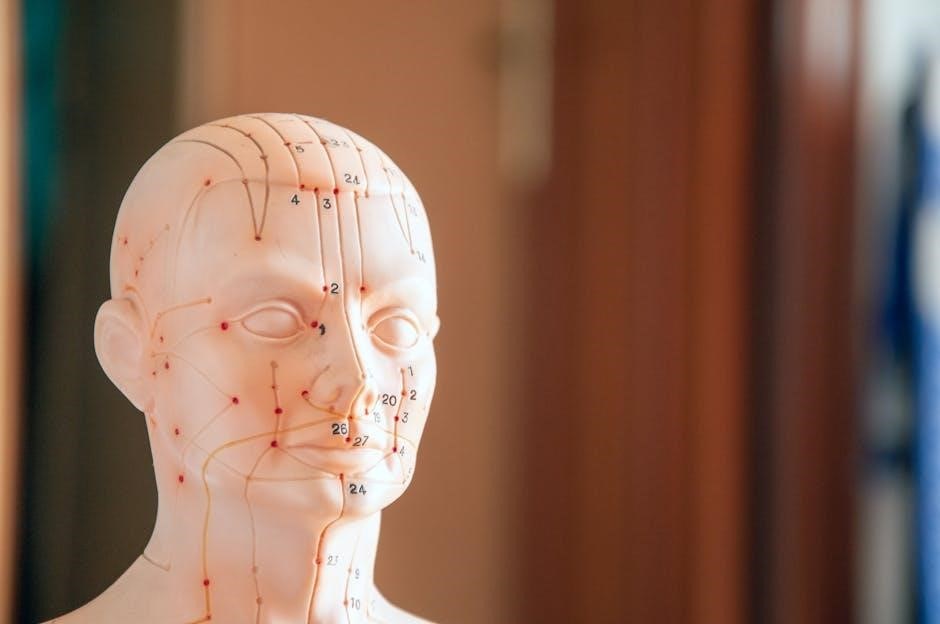
Key Anatomical Structures for Lab Study
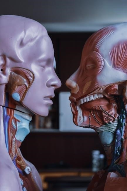
The lab manual focuses on major anatomical structures, including the skeletal, muscular, and organ systems. Students explore bones, joints, muscles, and vital organs like the heart and lungs.
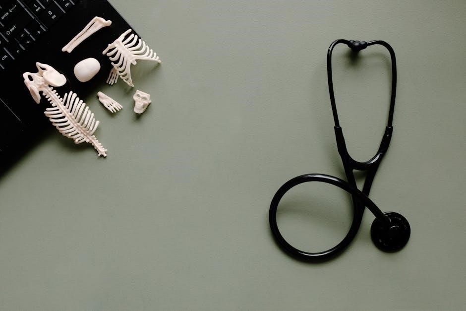
5.1 Human Skeletal and Muscular Systems
The human skeletal and muscular systems form the structural and functional framework of the body. The skeletal system includes bones, cartilage, and joints, providing support and protection. The muscular system comprises voluntary and involuntary muscles, enabling movement and maintaining posture. Lab exercises focus on identifying bones, such as the femur and humerus, and muscles, like the biceps and quadriceps. Students also explore joint types and their roles in mobility. Understanding these systems is vital for analyzing human movement and overall physiology.
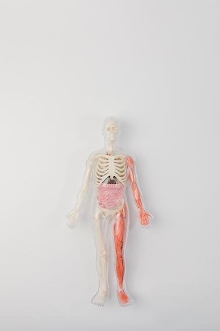
5.2 Major Organs and Their Functions
Major organs are essential for maintaining bodily functions, with each serving a unique role. The heart pumps blood, while the lungs facilitate gas exchange. The liver detoxifies and metabolizes substances, and the kidneys filter waste. The brain controls nervous functions, and the pancreas regulates blood sugar. Understanding these organs’ structures and functions is crucial for lab studies, enabling students to appreciate their interdependence and importance in overall physiology. Lab exercises often involve identifying and analyzing these organs to reinforce their critical roles in human health.
Lab Report Writing and Documentation
Lab reports document experimental procedures, results, and conclusions, ensuring clarity and accuracy. Proper formatting and organization are essential for effective communication of scientific findings and data analysis.
6.1 Structuring a Lab Report
6.2 Recording Observations and Data Analysis
Recording observations accurately is crucial for reliable data analysis in anatomy and physiology labs. Use clear, concise language to document findings, employing tools like tables or graphs for visualization. Ensure measurements are precise and validated through repetition or peer review. Data analysis involves interpreting results, identifying patterns, and drawing conclusions based on experimental objectives. Proper documentation practices, such as dating entries and maintaining legibility, ensure transparency and reproducibility of experiments, fostering scientific integrity and facilitating future reference or verification of findings.
Resources and References
Key resources include textbooks, online tools, and study guides to supplement lab learning, ensuring comprehensive understanding and practical application of anatomy and physiology concepts effectively.
7.1 Recommended Textbooks and Online Tools
Essential textbooks like Gray’s Anatomy and Human Anatomy & Physiology provide detailed insights into anatomical structures and physiological processes. Online tools such as Kenhub, Visible Body, and AnatomyTOOL offer interactive 3D models and virtual dissections, enhancing lab preparation and understanding. These resources are selected for their comprehensive coverage, visual aids, and practical applications, ensuring students have access to both foundational knowledge and modern learning technologies to excel in their anatomy and physiology studies.
7.2 Additional Study Materials for Lab Preparation
Besides textbooks, atlases like Netter’s Atlas of Human Anatomy provide detailed visuals for anatomical study. Flashcards and study guides, such as those from Quizlet, reinforce key terms and concepts. Video tutorials and lab simulations, available on platforms like YouTube and Labster, offer step-by-step guidance for complex procedures. Additionally, mobile apps like Complete Anatomy and Muscle Premium facilitate interactive learning. These resources complement traditional materials, ensuring a well-rounded and engaging approach to anatomy and physiology lab preparation.